[1]
Background
Whilst
latitude had been known and calculated for centuries the same cannot be said
for measuring longitude, that essential east and west component of a ship’s
position. The early navigators exploring and discovering new worlds relied on
what became known as latitude or parallel sailing. Not knowing their longitude
they followed a southerly course, often along a known coastline before sailing
a constant latitude east or west to their destination. Christopher Columbus’s
first voyage illustrates this method.
On his first voyage (the blue line on the map), in 1492, he
followed the known voyage to the Canary Islands where he carried out repairs
before setting out on a westerly parallel course until he discovered an island
in the Bahamas. For his return voyage he went northerly until he reached the
latitude of Lisbon when he started his easterly latitude sailing. It is
important to remember that navigation was relatively crude in this period and
charts covered only a small part of the Atlantic Ocean so latitude sailing from
a known departure point was a relatively low risk navigational strategy.
On later voyages, as his knowledge of the Atlantic grew and
his charts improved, he took more direct routes as shown in his fourth voyage.
This type of navigational voyaging continued as finding
longitude at sea proved an elusive target.
Some 200 years later the search for a method for determining
longitude became acute.
Sir Cloudesley Shovell as Commander in Chief of an English
naval fleet of 21 ships was returning from activities in the Mediterranean and
experienced bad weather on the northward leg of the voyage through the Bay of
Biscay without satisfactory plotting of his position. Relying on soundings he
believed he was north and west of Ushant on the northern French coast and
therefore turned to a NE’ly course to enter the English Channel.
However he was much further north and west, and his course
now led him to disaster on the outlying skerries of the Scilly islands off SW
England.
In
the evening of 22
nd. October 1707 the fleet struck the outer rocks,
and four ships were lost with an estimated loss of life of between 1500 and
2000 men including their Commander in Chief.
Much analysis of the logs of surviving ships placed the
navigational errors on poor navigation with poor equipment. For instance only
four of the surviving 112 compasses from nine ships were serviceable.
This disaster perhaps accelerated the search for a method to
calculate longitude as in 1714 a group of merchants and mariners petitioned
Parliament to solve the longitude problem. This resulted in the Longitude Act
of 1714 offering a prize of £20,000 for a method that could determine longitude
to an accuracy of half a degree.
However
already in 1713 two mathematicians had applied for financial support from
Parliament as they had found method to find longitude at sea.
A letter written in a newspaper by William Whiston and
Humphrey Ditton stated:
“‘We are ready to disclose it to the
world, if we may be assured that no other persons shall be allowed to deprive
us of those rewards which the public shall think fit to bestow for such a
discovery; but do not desire actually to receive any benefit of that nature
till sir Isaac Newton himself, with such other proper persons as shall be
chosen to assist him, have given their opinion in favour of this discovery.’”
(“The original copy of the 1714 Longitude
Act in the Parliamentary Archives”)
So already before the Act came into force the
scientific academic community was laying claim to the discovery. Note that the
assistance of Isaac Newton to assist. The problem was that the method was
completely impractical requiring ships at known locations firing rockets at
fixed times. On 25th. May of that year Parliament considered the
application and by July the act became established, and a Board of Longitude
created made up of scientists and astronomers who would oversee submissions for
the prize. So the scene was set for astronomers to develop a method of
calculating the moons motion to establish Greenwich Mean Time. The problem was
that it was a complicated process thought beyond the capabilities of seafarers
although Captain Cook did commend it on his first voyage albeit he had an
astronomer on board at the time to carry out the calculations.
The battle to win the prize
There were two challenges to be overcome, one technical and
one political.
The technical issue
This relates to understanding the nature of longitude.
Circles of longitude are “great circles” as their diameter is the same as that
of the earth and they all pass through the poles. They are often called meridians,
and their angular distance apart determines their location, and they are
measured east and west of the “prime meridian” which is set at 0 degrees and which
today is Greenwich in the UK.
This meridian divides the earth into two hemispheres east and west.
As the earth rotates 360 degrees in 24 hours, so each 15
degrees of longitude passes in one hour.
So it seems relatively simple to measure longitude. The
seaman determines his local time from observations of the sun and compare it
with the time back home at the same moment he derived local time. The
difference in time can then be calculated as a difference in longitude knowing
the longitude of the home base. For example, if the time is 1300 local time
when the suns meridian passage is measured it is 1200 GMT (Greenwich Mean Time)
at Greenwich the ship is 1 hour ahead of Greenwich meaning 15 degrees east.
That seems simple but you need a clock on
board that is accurate because 1 degree of longitude equals 4 minutes of time
but in terms of distance, one degree at the equator is 60 nautical miles
reducing to zero at the poles. Such accuracy in clocks was not possible in the
early 1700’s.

The accepted method of determining longitude in the late 17th.
and early 18th. century was by the measurement of the angular
distance between celestial objects, ideally the moon and the sun, called the
lunar distance method.
As the moon travels across the background of stars and the sun it was possible
to take the measured angular distance, look up its value in a published
nautical almanac and find the GMT (Greenwich Mean Time) for that measurement.
In the example, finding the lunar distance between a star and the moon will
give a time.
Once the GMT or any other reference time and location is determined the local
mean time (LMT) of the sun’s meridian passage can be found from the Nautical
Almanac
and the time difference between GMT and LMT can be translated into longitude.
This is a simplified version what, is a long and complicated
calculation but central to the method is the accurate measurement of time. In
trials of the lunar method at sea in 1764 mariners stated it took around 4
hours to determine longitude.
The political dimension
The competitive nature to find a method by the lunar
distances to measure longitude was European wide amongst the astronomers of the
day. France, had worked to refine tables and produce the Nautical Almanac to
assist in the measurement of celestial objects as a basis to determine
longitude.
King Charles II promoted the UK’s bid for astronomical
supremacy with the building of the Greenwich Observatory in 1676 and the
appointment of an Astronomer Royal, John Flamsteed.
So the scene was set for scientists to research methods to determine longitude.
Over the following
100 years subsequent Astronomer Royals sought to research and promote the Lunar
Distance method and capture the prize for determining longitude at sea.
A Board of Longitude was responsible for determining whether
any method submitted to them met any of the three criteria:
A £20,000 prize if the method had an accuracy of ½ degree of
longitude
A £15,000 prize if the method had an accuracy of 2/3 degree
of longitude
A £10,000 prize if the method had an accuracy of 1 degree of
longitude
Neville Maskelyne,
the fifth Astronomer Royal who was the most ardent advocate of the lunar
distance method carried out numerous voyages to promote this method and claim
the prize.
The challenger
John Harrison was a carpenter born in Yorkshire in 1694 with
a fascination for clocks. At the age of 20 he built his first pendulum clock
made entirely of wood.
He continued to experiment with clock-making and around 1722
was commissioned to build a tower clock for Sir Charles Pelham. That clock
still runs some 279 years after.
With
further experiments he refined his clocks so that by 1727 they had an error of
one second in a month compared with contemporary watches of the time that had errors
of one minute every day!
If he could design a clock with such accuracy that would work in the harsh
maritime environment, he could challenge the scientists and claim the Longitude
prize.
This led him to enter the race to find longitude, a time-based
calculation, in competition with the scientists approach with the lunar
distance method.
Over the next 40 years he designed and built 4 clocks. The
first attempt, H1, was a monster of a clock weighing 34 kilos and housed in a
1.2m casing.
It went on trial at sea and performed well.
The results were presented to the commission in 1737, and they were pleased
.
Harrison, however, was critical of the watch and suggested he could improve on
it. The commission agreed and gave him finance to continue.
For the next period of around 20 years Harrison produced further improved
clocks H2 and H3, neither of which made it to the seaborne trials.
During this period two things emerged to challenge Harrison’s
work. First, around 1730 John Hadley produced a device that could more
accurately measure angular distance, the octant.
This would benefit both the measurement of lunar distance and the measurement
of the altitude of the meridian passage of the sun.
Neville Maskelyne also continued to refine the lunar
distance method of determining longitude.
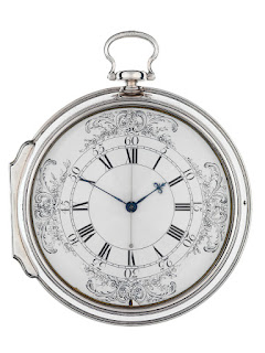
[28]Harrison
produced his fourth clock, H4, called a sea clock around 1755. What was
remarkable about it was that it was only slightly larger than a pocket watch. So
the scene was set for another dual with the scientists using the lunar distance
method.
A final test of both methods was conducted in 1764 by
voyages to Barbados to determine its longitude. Harrison was now in his 70’s
and his son, William, took over the care of the sea clock on the voyage.
On their return and examination of the results the
Commission were convinced that Harrisons Sea clock, the Chronometer, was the
winner as the clock only lost five seconds on an arduous 81 days at sea.
Captain Cook had only praise for the watch calling it “our
trusty friend, the watch”.
So from a demand by seafarers in 1714 for a reliable method of determining
longitude to approval by one the foremost navigators of the time vindicated
Harrisons struggle to demonstrate his prowess as a clock maker for maritime
use.
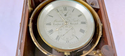
So the birth of the chronometer was assured but it was expensive,
and it took another 100 years before it was found regularly on merchant ships.
[31]
Fast
forward to the 1960’s when I was at sea and the chronometer was an essential
instrument for determining the ship’s position. It was most often housed in
gimbals in a glass case to the left of the chart table. In the ships I sailed
on there was always two chronometers. It was wound regularly at the same time
of day and the responsibility was that of the second officer whose main duty
was as navigator. One of the important tasks was to check the daily error of
the chronometer and this was done by listening to the BBC Greenwich Time signal
or “pips” as they were called. Six electronically derived signals that precisely
measured the time on each hour.
Postscript
The measurement of time has always been crucial to fixing
location and even today with GPS it requires an accurate satellite time signal
to fix position. Threats to GPS position setting have been interrupted by GPS
jamming where the satellite time signal is compromised. This is a serious
breach to GPS position fixing and new methods are required to provide an
accurate time signal. One
British research project will place a local time signal generator in your watch
or mobile phones so removing the need for a satellite time signal. We must wait
and see if GPS jamming can be avoided.
References
American Scientist. ‘The British Longitude Act Reconsidered’, 6
February 2017. https://www.americanscientist.org/article/the-british-longitude-act-reconsidered.
‘Greenwich Time Signal’. In Wikipedia,
8 January 2025.
https://en.wikipedia.org/w/index.php?title=Greenwich_Time_Signal&oldid=1268182904.
‘H4 | Royal Museums Greenwich’. Accessed
4 March 2025. https://www.rmg.co.uk/collections/objects/rmgc-object-79142.
‘History of Royal Observatory Greenwich |
Home of GMT’. Accessed 28 February 2025.
https://www.rmg.co.uk/royal-observatory/history.
‘John Harrison’. In Wikipedia, 1
March 2025.
https://en.wikipedia.org/w/index.php?title=John_Harrison&oldid=1278206504.
‘Kronometer’. Accessed 24 January 2025.
https://digitaltmuseum.no/011022541437/kronometer.
‘Letter Claiming Discovery’. Accessed 24
January 2025.
http://www.royalobservatorygreenwich.org/articles.php?article=1312.
‘Longitude Found - the Story of
Harrison’s Clocks | Royal Museums Greenwich’. Accessed 24 January 2025.
https://www.rmg.co.uk/stories/topics/harrisons-clocks-longitude-problem.
Longitude Prize. ‘The History’. Accessed
24 January 2025. https://amr.longitudeprize.org/the-history/.
‘Lunar Distance (Navigation)’. In Wikipedia,
28 January 2025.
https://en.wikipedia.org/w/index.php?title=Lunar_distance_(navigation)&oldid=1272314357.
‘MV Akdeniz - Photo Page 2’. Accessed 4
March 2025. http://ssmaritime.com/Akdeniz-5.htm.
‘Nautical Almanac’. In Wikipedia,
25 February 2025.
https://en.wikipedia.org/w/index.php?title=Nautical_almanac&oldid=1277512307.
‘Nevil Maskelyne’. In Wikipedia,
15 December 2024.
https://en.wikipedia.org/w/index.php?title=Nevil_Maskelyne&oldid=1263169488.
‘Octant (Instrument)’. In Wikipedia,
10 January 2025.
https://en.wikipedia.org/w/index.php?title=Octant_(instrument)&oldid=1268610567.
‘Plane GPS Systems Are under Sustained
Attack - Is the Solution a New Atomic Clock?’, 3 March 2025.
https://www.bbc.com/news/articles/cq6yg204pvmo.
‘Royal_Observatory.005_-_Greenwich_(London).Jpg
(4000×3000)’. Accessed 3 March 2025.
https://upload.wikimedia.org/wikipedia/commons/5/55/Royal_Observatory.005_-_Greenwich_%28London%29.jpg.
‘Scilly Naval Disaster of 1707’. In Wikipedia,
2 December 2024.
https://en.wikipedia.org/w/index.php?title=Scilly_naval_disaster_of_1707&oldid=1260750007.
Sobel, Dava. Longitude: The True Story
of a Lone Genius Who Solved the Greatest Scientific Problem of His Time.
First. Bloomsbury USA, 2007.
‘The Quest for Longitude and the Rise of
Greenwich - a Brief History’. Accessed 28 February 2025. https://www.royalobservatorygreenwich.org/articles.php?article=1290.
‘Voyages of Christopher Columbus’. In Wikipedia,
17 January 2025.
https://en.wikipedia.org/w/index.php?title=Voyages_of_Christopher_Columbus&oldid=1269955043.
‘What Is the Prime Meridian, and Why Is
It in Greenwich?’ Accessed 28 February 2025.
https://www.rmg.co.uk/stories/topics/what-prime-meridian-why-it-greenwich.
 [1]
[1]


.jpg)


.jpg)


